Nicholas Fluhart

May 26, 2013

Project Loadstar: Step Board Repairs

Filed under: Project: Loadstar,Trucks & Equipment — Nicholas Fluhart @ 7:14 pm

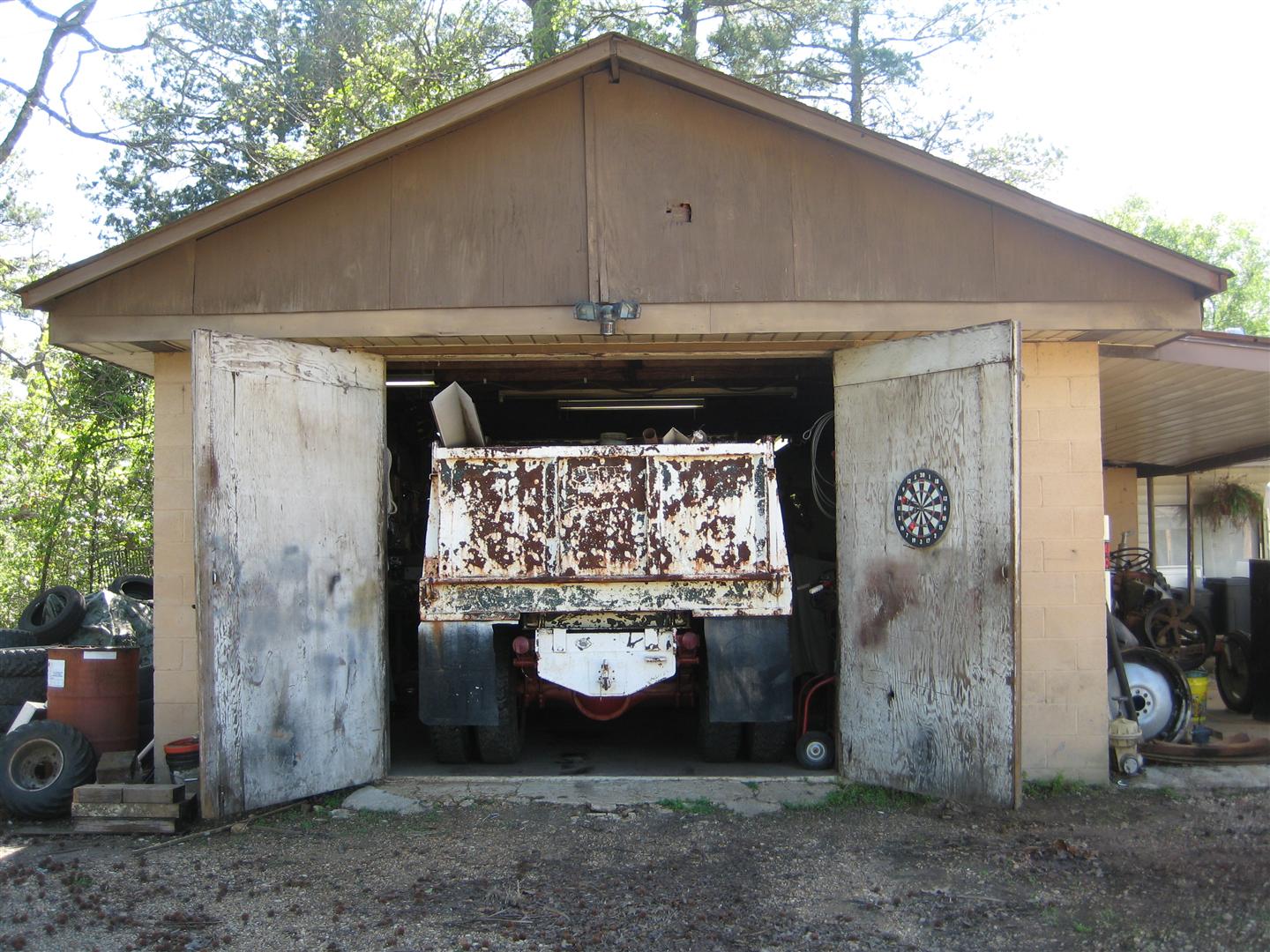
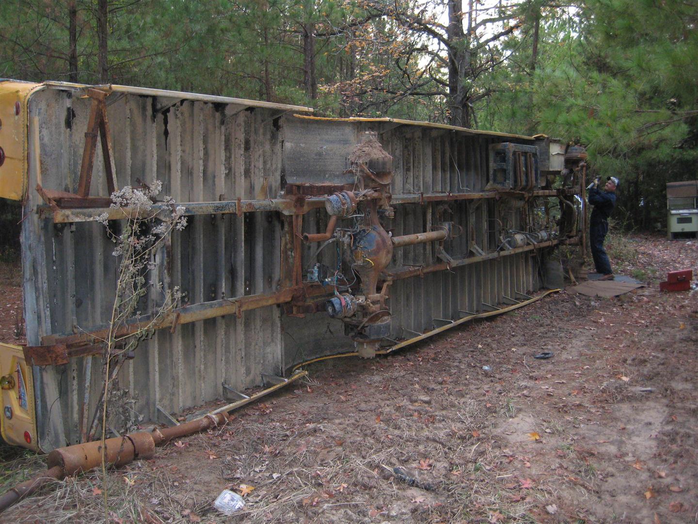
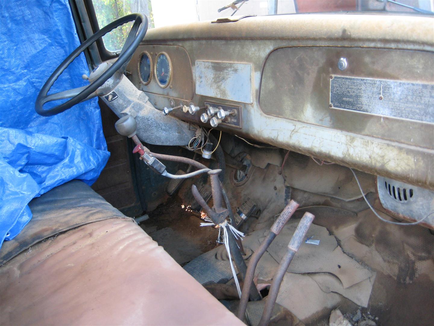
This installment of the Loadstar Project will cover repairing the drooping step boards that are such an eye sore. In the photo below, you might notice the step board below the door appears to be bent down. This tends to happen on the old Loadstars because there is very little support for the step mounts. They basically hang from the lower edge of the cab’s sheet metal. The front is supported by the front fender, but the rear has no other support and subsequently fatigues the cab sheet metal which allows it to swing back in toward the frame and droop.

Right Side

My first thought was to install a brace from behind the step to the frame. This would effectively push the step up level and hold it there. However, the problem with the passenger side is that the fuel tank is located directly behind the step, and there’s no easy way get around it. So for this side, I decided to use my welding machine to repair the original mounts at the sheet metal. Fortunately, this was doable because the passenger side step board was in better shape than the driver side because it likely saw less use. My welding machine is an antique Westinghouse AC arc welder so using it, or any arc/stick welder, to weld sheet metal is very difficult . These types of welders are designed to weld thicker material and easily burn through sheet metal leaving the metal more damaged than when you started. Nevertheless, it’s all I have so I’ll have to be precise. I put a bottle jack under the step board to push it up to it’s correct position. I then turned my welder down to a low setting and commenced on dressing the fatigue cracks in the sheet metal around the mounting bolts. Then I went ahead and welded the step board directly to the cab in a few spots for added stability. When I lowered the bottle jack, the step board stayed put. I stood on it, putting my full weight on the outside corner, and it is now very solid. Success.

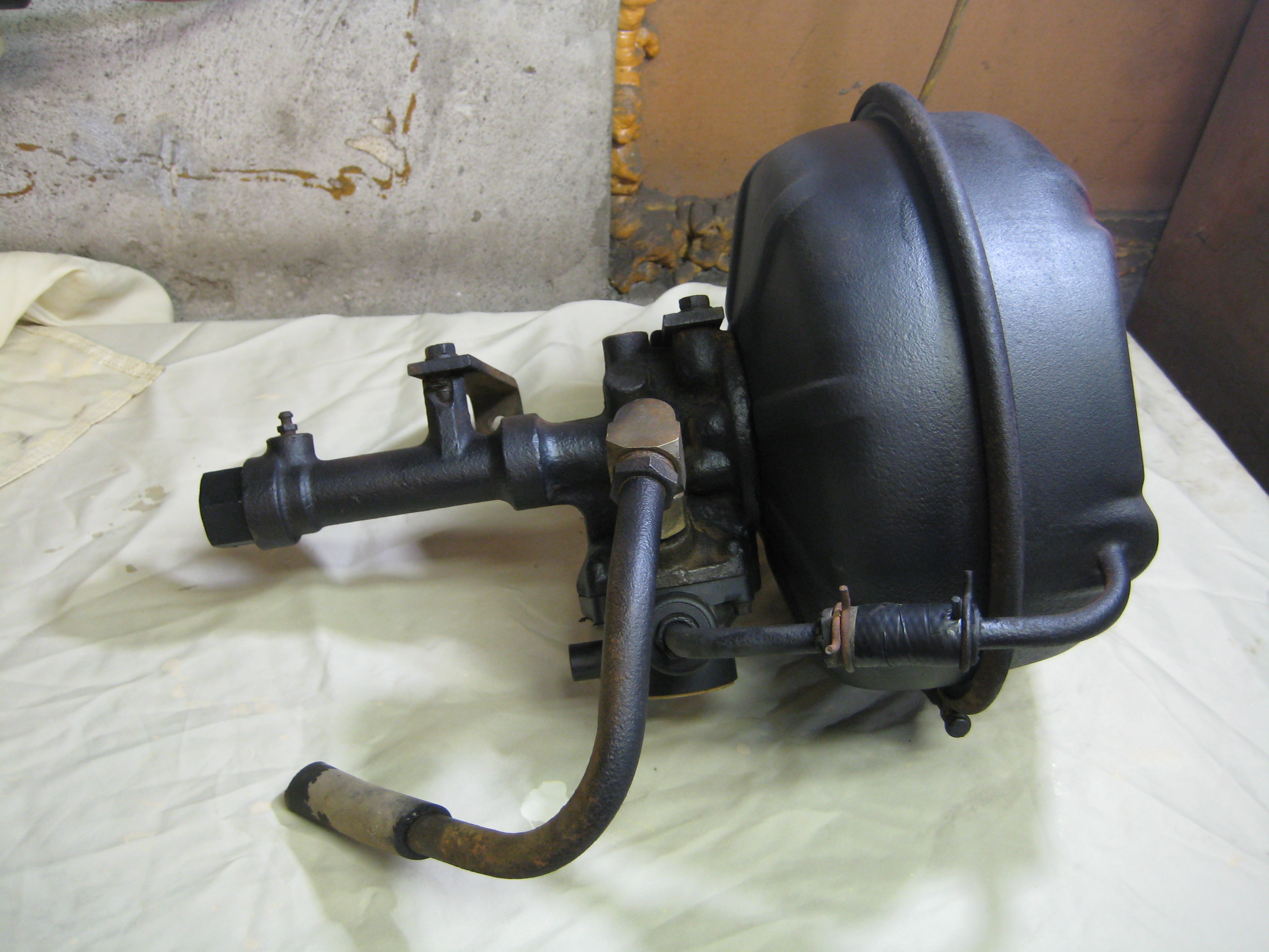
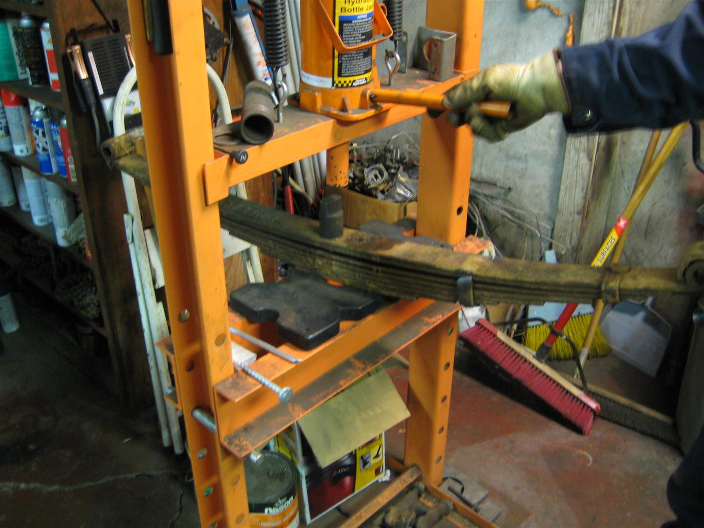
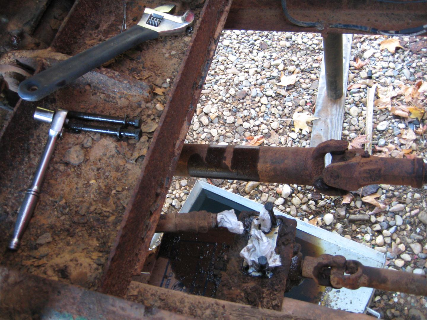
I turned my attention to the driver side. I attempted to repair it in the same manner discussed above, but it was too far gone so I returned to my original idea of installing a brace. Since there is plenty of room behind the step board and to the rear of the hydrovac booster, I could easily weld a support from the back of the step board to the frame of the truck. I browsed my scrap pile for something I could use as a brace and I found the perfect item. It’s a piece of leaf spring left over from the leaf spring project. This is why it pays to keep junk around.

Leaf Spring Piece
I turned my welding machine back up to handle the thicker material, and then I found a suitable, effective location for the brace and welded it in place.

Step Board Brace
It worked perfectly. I can now do jumping jacks on the step board, if I’m so inclined to do so, and it will easily hold my weight without sagging into its prior cosmetic abomination.

That concludes this seventh installment of the Loadstar Project. Next I’ll address some dump bed repairs. Until then…

May 19, 2013

Project Loadstar: Brakes Part 2

Filed under: Project: Loadstar,Trucks & Equipment — Nicholas Fluhart @ 11:19 pm
Tags:

Time for some power brakes! In this sixth installment of the Loadstar Project I’ll be addressing the power brake booster, sometimes referred to as a “hydrovac”. Into the shop it goes…
Dump Truck In Shop 1
Dump Truck In Shop 2
Now this has been one of the more “pain in the neck” repairs I’ve done to this truck. First off, I knew the main diaphragm in the brake booster was bad. I had a similar booster from my F-700 with a stuck piston but a good diaphragm. I was desperately hoping all I needed for mine was the diaphragm because parts for these, specifically an overhaul kit, are expensive and hard to find. If I could switch out the diaphragm with the F-700 unit, it would be an easy fix. These boosters are not even made anymore, and although a remanufactured booster can be had for around $250.00, I really hadn’t budgeted that in to this project.

So once I had it in the shop I rolled under the truck to begin. The lines and fittings looked rusty and hard to remove, so at first I thought I would try to repair the booster with it mounted on the truck. I removed the main diaphragm cover to reveal, as anticipated, a broken diaphragm. What I did not anticipate was that half of the chamber would be full of old brake fluid which splashed everywhere and was the actual cause of the deteriorated diaphragm. Now, bare in mind this is supposed to be a dry chamber, so the fact that it is full of brake fluid reveals a more sinister problem than a broken diaphragm. It means the piston rod seal is leaking fluid from the cylinder into the diaphragm chamber. This explains why the previous owners told me they were having to add fluid, thinking it was a leaky wheel cylinder.

Time to find an overhaul kit. I searched high and low and found nothing. Finally, I happened across a brake parts remanufacturer’s website called remaninc.com. They had a series of kits in their online catalog, so I just needed to figure out which type of booster I had and locate the correct part number. Like all boosters are supposed to have, there was an aluminum tag on the unit with a series of numbers. These numbers identify the brand and model of booster. I made note of my numbers and searched the website for the rebuild kit for my unit. Unfortunately, my number didn’t pull up anything. However, as a last resort, I called the phone number on the website and they actually have a parts counter for customer support. Surprisingly, the guy I spoke with knew exactly what I had and exactly the correct kit I needed, which they had in stock by the way, and he shipped it out that same day. If I remember correctly, I think the cost was about $85.00. I couldn’t be happier.

So trying to do this with the unit still on the truck, I now have to remove the steel brake line and the end of the cylinder which is a large nut as seen below, so I can slide the piston and rod out in order to replace the leaking seal:

Cylinder End

Chamber Side
Removing Piston
I went ahead and removed the smaller diaphragm on the bottom along with the springs and other components as everything would have to be cleaned thoroughly and seals replaced.

Small Diaphragm Chamber
Now I have to remove the main shaft seal and “retainer” for lack of a better word. This is where the problems begin. The seal and retainer are pressed in. Once the piston was out, I removed the appropriate snap rings and tried to use a punch to drive out the retainer. Fail. I hit it with everything I had and it didn’t budge a bit. It was at this time that I determined I would have to remove the entire unit from the truck so I could put it in my hydraulic press. Below you’ll see a photo of the chamber side. In the very center is the part that I have to press out from behind once the snap ring is removed.

Chamber Side
To fit the part in my press, I remove the chamber housing and put the cylinder in the press as shown below:

Cylinder In Press
I didn’t have much problems pressing out the retainer and spacer, but the parts being plastic were slightly damaged. Unfortunately, the kit did not come with replacements so I’d have to repair these and reuse them.

Seal Retainer & Spacer
So now that I had the entire unit disassembled, it was time to clean. No easy task. As seen below, the parts were heavily rusted. I could only hope the cylinder would take a rebuild, otherwise I just wasted $85 on the kit.

Booster Parts
I washed everything in my parts washer and air dried it before bead blasting in my blasting cabinet. I laid out all the parts and the rebuild kit along with the instructions.

Booster Rebuild Kit
Cleaned Parts
I polished the piston and rod with a wire wheel so the seals would travel smoothly. Then I installed the piston cup seal. I also honed out the inside of the cylinder with a brake cylinder hone.

Piston

I pressed the seal retainer with the new rod seal and o-ring into the cylinder. Then the entire unit is reassembled the same way it came apart. Now it’s ready to go back on the truck.

Brake Booster
Once back on the truck, I manually bleed the system. When adequately bled, the moment of truth arrives. It’s easy to tell if the diaphragm portion works. I start the truck and if the engine dies when I push the brake pedal, the diaphragm is bad. If it stays running and I hear a vacuum sound, it’s good. As for the cylinder portion, I would have to drive the truck to test it.

The verdict: I start the truck and push the pedal. The engine stays running and I hear the booster working. So far so good. I drive the truck out of the shop and hit the brakes hard. The wheels easily lock up. Success! I drive it around the yard and test it thoroughly. I then re-check my brake fluid level. Looks good. The only unusual thing about it is that the brakes are a little slow to release. Other than that, everything works. I now have power brakes on my Loadstar!

May 12, 2013

Project Loadstar: Chassis

Filed under: Project: Loadstar,Trucks & Equipment — Nicholas Fluhart @ 6:14 pm

After the leaf springs were successfully installed, I decided to paint the chassis and select the tires to be used. Choosing which color to paint the chassis will depend on the color of the cab and other components. While the truck was currently sporting, albeit severely weathered, a red cab, white bed, and dirt colored chassis, the original color of this truck was green. There are a variety of good looking paint schemes that I could use. However, one thing is for sure, I’m not big on “bling”. Rather, I want something industrial and period correct. I had a few ideas rolling around in my mind when my dad happened to bring by the latest issue of Classic Plant and Machinery. The cover features an old dump truck and wheel loader. Although the truck on the cover is not an International, I like the classic paint scheme and I think with a little modification I could create a similar scheme that would look great on a Loadstar. Below is a pic of the magazine cover:

CPM-latest
You’ll note the green cab, black bumpers and red chassis. For my Loadstar, I decided on a green cab and red chassis while the bed, fenders, and bumpers would be black. Once I visualize a finished product, the excitement carries me through all the hard work to complete the project. So here we go…

The first order of business was to find some decent tires. The current tires are 8.25-20 and severely weathered beyond use. I didn’t want to buy brand new tires for a truck that I would only use once in a blue moon, so I decided to pull the wheels from my decommissioned F-700 winch truck. They are slightly weather checked but are light-years ahead of the Loadstar tires and will work fine for occasional use. Slightly larger, they are 9.00-20 already on Dayton rims, so they should bolt right on. We pulled the old wheels off the Loadstar, carried them out to the country and swapped them out on the F-700. Once I got the 9.00-20’s home, I steam cleaned them.

Wheels Hauled Home

Cleaning Tires
Since the chassis had so many years of caked on dirt, sand, crude oil, and asphalt, it required thorough wire brushing (we used a knotted cup brush on an angle grinder) and washing. Once adequately cleaned, we first primered the chassis and then painted it red. I used Regal Red oil based industrial enamel with a catalyst hardener added for durability.

Chassis Primered
Chassis Painted Regal Red
Front Axle Regal Red
Back to the wheels. I’ll note, the rims with the 9.00-20’s from the F-700 are wider than the rims that came on the 1600 Loadstar. The rears fit fine, but the fronts rubbed the tie rod ends so we had to break down the front tires and mount them on the original narrow front rims. Not fun, but it had to be done.

Tire Break Down Narrow Rim

I painted the rims black with silver around the outer edge. Here’s what they look like on the truck…

Rear Wheels Wheels Installed

That wraps up the fifth installment of the Loadstar Project. More to come…

May 5, 2013

Project Loadstar: Front Leaf Springs

Filed under: Project: Loadstar,Trucks & Equipment — Nicholas Fluhart @ 5:38 pm
Tags: ,

The next issue I decided to address, and the topic of this forth installment of the Loadstar project, is the front suspension.

I noticed the truck sitting low in the front, and with 8.25-20 tires, the wheel wells shouldn’t be so full. I crawled under to take a look and the problem was immediately noticed. The front springs are worn out. A leaf spring should have a natural arch to it. These were collapsed and the shackles were flattened back. Well, that explains the low ride height, now the question is what can I do to fix it?

Hard parts are a challenge because they are hard to find in my area. While there was an International dealership here years ago, surviving Loadstar trucks are virtually non existent around here.  I thought about repairing my existing springs. I know leaf springs can be “re-sprung” by putting them in a fixture, heating them evenly, and then applying a cooling process. The only problem is that I have no idea what that process is or what’s involved. If done improperly, the springs will be weakened and useless. So I quickly ruled out fixing what I have. The next possible solution is to find a set on another type of truck and modifying them to work on my truck. I would essentially build my own springs using parts from both. That sounds much more feasible.

So I set out to find a donor truck. The most common trucks around here are Ford F-600, F-700, etc. The good news is, I have a friend with a junk yard who has several of these old trucks. The bad news is, the Ford leaf springs mount differently than my International springs, so we would have to do something to make it work. Nevertheless, after wondering around in the woods my helper and I found a good donor truck: a Ford B-700 school bus laying on its side.

Donor TruckThe bus springs were thicker than the Loadstar springs, and they were in great shape. They’ll do just fine. Since the bus was on its side for whatever reason it made it very easy to get to the springs, which are very heavy by the way. Once back at the shop, we made some comparisons. Although the bus springs were thicker, they were the same width as mine which will make our job easier. Furthermore, we decided to use the top spring from the Loadstar, so the mounts and attachment length would be correct for the frame. We would then attach the rest of the leaves from the bus springs under the top spring providing more than adequate spring capability. This requires disassembling both sets of springs, matching up the proper number of leaves, and then assembling the new combination. We use a torch to cut off the old brackets and rivets not to be used.

Disassembling Leaf Spring

Then we put the assembly in the hydraulic press, loosened the center bolt that holds the springs together, and slowly let the pressure off.
Reassemble In Press

We match up the leaves to be used and assemble the spring.

Leaves Matched Up

Here’s the finished spring…

Spring

Now, before we can reinstall it on the truck, I have to address another problem that was reveled when we removed the springs: worn out shackle bushings and pivot bolts. From lack of lubrication, the bushings were worn through completely, and the bolts were almost worn in half.

Worn Shackle Bolt
I jumped online and surprisingly located some new bushings.

New Bushings

To save on cost, I decided to repair the worn pivot bolts instead of replacing them. I welded in the worn area on each bolt to build it up to the proper thickness. It took a few passes with my antique Westinghouse A/C Arc Welder.

Worn Bolt Welded Bolt

Ideally, a machinist’s lathe would be used to turn the bolt back into the correct diameter. However, I don’t have a lathe. So in lieu of expensive machine tools, I carefully used my bench grinder to dress the bolt…and it turned out pretty good I must say.

Dressing the Bolt Finished Bolt

These bolts are hollow with a passage for grease to be pumped in at one end. The grease flows out to the bushing through a hole in the side of the bolt. To clear the weld from the grease hole, I finished up by using my drill press to re-drill the holes. The bolts fit into the bushings perfectly.

Spring Bolts/Bushings

Upcoming, we’ll address reinstalling the springs, finding some good tires, and other chassis related stuff. Until then…

April 28, 2013

Project Loadstar: Hydraulics

Filed under: Project: Loadstar,Trucks & Equipment — Nicholas Fluhart @ 6:56 pm
Tags: ,

In the third installment of the Loadstar project, I’ll be addressing the hydraulics that operate the dump bed. Like most IH trucks that were fitted with a dump body at the dealer, this truck has a GarWood hoist body, i.e. dump bed, produced by GarWood Industries founded by the famous inventor and boat builder/racer, Garfield “Gar” Wood.

The hydraulic system on this truck is fairly simple. The transmission has a power takeoff (PTO) operated from the cab. When the PTO is engaged, power from the engine is diverted through the transmission and out of the PTO via a drive shaft. The PTO drive shaft drives a hydraulic pump that provides pressure to the dump bed cylinder operated by the hydraulic valve which is engaged with a lever from the cab.

To start, and to make things a little easier, I used one of my forklifts to raise the dump bed enough to easily access most of the components.

Hydraulic Repairs

As I noted in the first installment of the Loadstar project, the PTO engages but the hydraulic valve doesn’t seem to be operating. To visually inspect it, I got my helper to crawl under the truck and watch the linkage while I operated the lever from the cab. Below you see the levers in the cab. We have the main gear shifter with the button for high and low range. The next lever to the right of the gear shifter is the parking brake lever. The next one to the right is the lever that operates the hydraulic valve. The next lever on the far right operates the PTO.

Levers in Cab

The linkage looked good, but we were able to determine that the plunger on the hydraulic valve was stuck from dirt and corrosion. We would need to remove the valve and disassemble it for cleaning. In the photo below, you see the view from the under side. The red mechanism with the drive shaft connected to it is the PTO on the side of the transmission. You can see the linkage connected to the PTO plunger going up to the lever at the right. The lever on the left would have linkage going to the hydraulic valve not shown, but we removed it before removing the hydraulic valve.

Under Side

In the photo below you see the other end (top side) of the PTO drive shaft (the smaller shaft in the lower right) which is connected to the hydraulic pump. The hydraulic valve mounts directly on top of the pump and is removed in the photo below.

Hydraulic Valve Removed
We took the valve into the shop to disassemble it. We removed the plunger and polished it with a wire wheel on one of my bench grinders.

Disassembling Valve
Once the valve was cleaned and reassembled, we cleaned the mounting area on the hydraulic pump and reinstalled the valve and hoses as seen below.
Valve Reinstalled

Now it’s time to fill the system with fluid. Most hydraulic systems have a stand alone reservoir which contains the hydraulic fluid. However, in this case the hydraulic cylinder itself has a self contained reservoir. Below you see a photo of the cylinder assembly. On each end of the cylinder there is a fill plug for adding the fluid.

Hydraulic Dump Cylinder

After everything was done, the moment of truth arrived. I started the engine, engaged the PTO, and pulled the lever operating the hydraulic valve, and…success! The dump bed works perfectly.

More fun stuff ahead. Until next time…

« Previous PageNext Page »

Blog at WordPress.com.