In the third installment of the Loadstar project, I’ll be addressing the hydraulics that operate the dump bed. Like most IH trucks that were fitted with a dump body at the dealer, this truck has a GarWood hoist body, i.e. dump bed, produced by GarWood Industries founded by the famous inventor and boat builder/racer, Garfield “Gar” Wood.
The hydraulic system on this truck is fairly simple. The transmission has a power takeoff (PTO) operated from the cab. When the PTO is engaged, power from the engine is diverted through the transmission and out of the PTO via a drive shaft. The PTO drive shaft drives a hydraulic pump that provides pressure to the dump bed cylinder operated by the hydraulic valve which is engaged with a lever from the cab.
To start, and to make things a little easier, I used one of my forklifts to raise the dump bed enough to easily access most of the components.

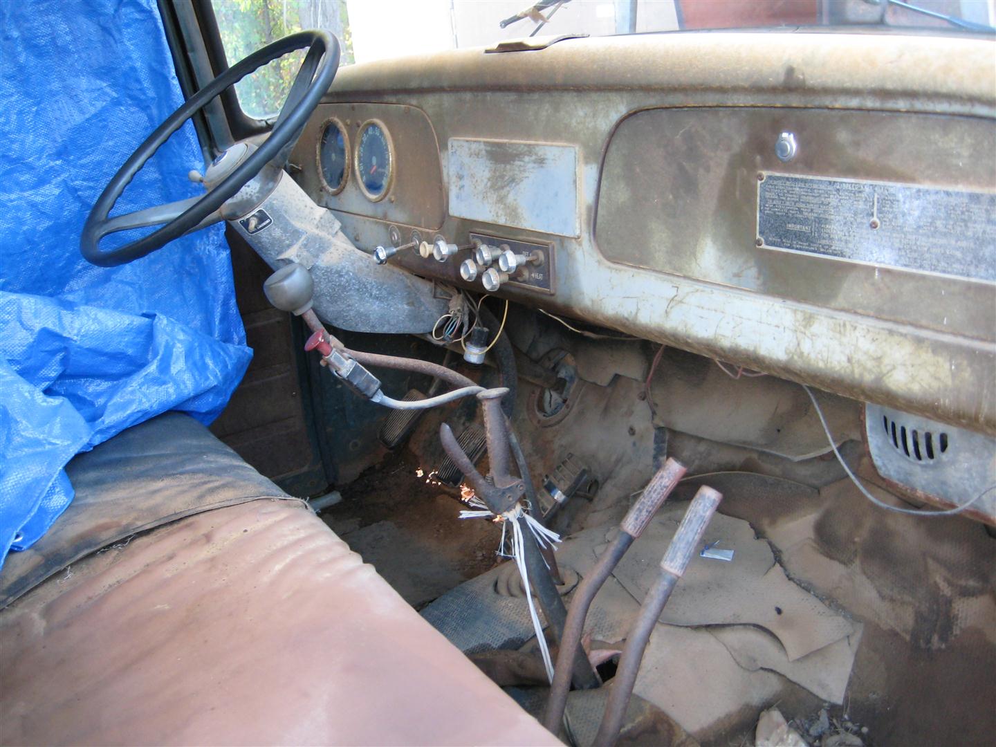
As I noted in the first installment of the Loadstar project, the PTO engages but the hydraulic valve doesn’t seem to be operating. To visually inspect it, I got my helper to crawl under the truck and watch the linkage while I operated the lever from the cab. Below you see the levers in the cab. We have the main gear shifter with the button for high and low range. The next lever to the right of the gear shifter is the parking brake lever. The next one to the right is the lever that operates the hydraulic valve. The next lever on the far right operates the PTO.
The linkage looked good, but we were able to determine that the plunger on the hydraulic valve was stuck from dirt and corrosion. We would need to remove the valve and disassemble it for cleaning. In the photo below, you see the view from the under side. The red mechanism with the drive shaft connected to it is the PTO on the side of the transmission. You can see the linkage connected to the PTO plunger going up to the lever at the right. The lever on the left would have linkage going to the hydraulic valve not shown, but we removed it before removing the hydraulic valve.

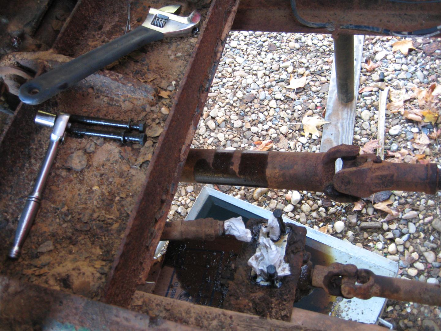
In the photo below you see the other end (top side) of the PTO drive shaft (the smaller shaft in the lower right) which is connected to the hydraulic pump. The hydraulic valve mounts directly on top of the pump and is removed in the photo below.
We took the valve into the shop to disassemble it. We removed the plunger and polished it with a wire wheel on one of my bench grinders.

Once the valve was cleaned and reassembled, we cleaned the mounting area on the hydraulic pump and reinstalled the valve and hoses as seen below.

Now it’s time to fill the system with fluid. Most hydraulic systems have a stand alone reservoir which contains the hydraulic fluid. However, in this case the hydraulic cylinder itself has a self contained reservoir. Below you see a photo of the cylinder assembly. On each end of the cylinder there is a fill plug for adding the fluid.

After everything was done, the moment of truth arrived. I started the engine, engaged the PTO, and pulled the lever operating the hydraulic valve, and…success! The dump bed works perfectly.
More fun stuff ahead. Until next time…


Leave a comment