Nicholas Fluhart

March 30, 2013

Ditch Witch R40 Drive Chain

Filed under: Project: Ditch Witch,Trucks & Equipment — Nicholas Fluhart @ 6:48 pm

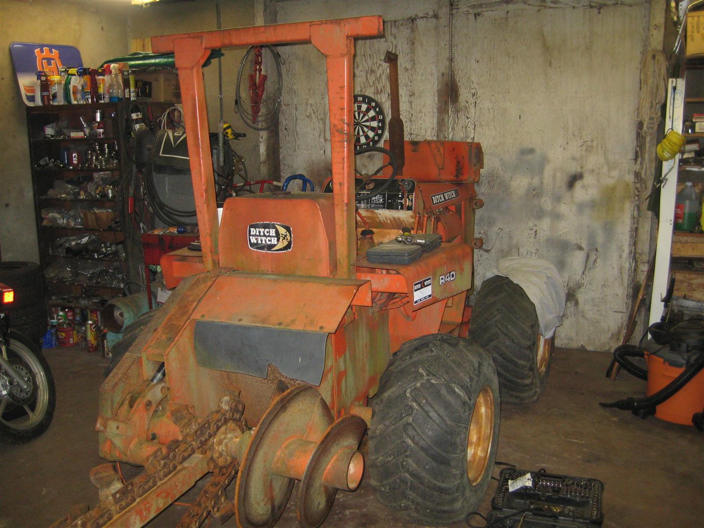
After using the Ditch Witch a few times, it became evident that it would be much easier and quicker to get around on it if the main drive chain was fixed. The 40 feet per minute, or whatever it is that the hydraulic drive produces, just didn’t cut it. So, we pulled it up in my shop and Philip began removing the damaged sprocket from the transfer case. The large sprocket coming from the transmission was fine, so he just needed to remove the small one.

Ditch Witch in the Shop

In order to do this, the brake rotor must be removed from the rear drive shaft and the transfer case has to be loosened and moved forward slightly to allow enough clearance for the rotor to drop out. The sprocket slides on the transfer case shaft on a key way and is held in place with a set screw. Upon closer inspection, it became evident that someone had tack welded the sprocket on the shaft. So Philip had to grind the weld off, which was not easy in such a tight space, then the sprocket slid off. In the next photo you see the shaft where the sprocket was removed and below the shaft, you see the loose bolts where the brake rotor was removed.

Removed from Shaft

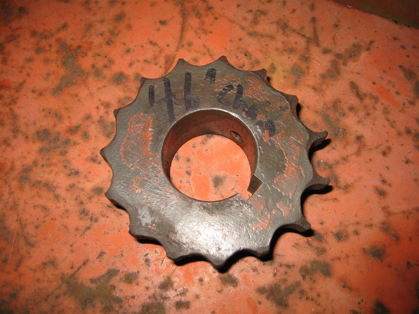
And here’s a shot of the old sprocket. Definitely time to replace…

Sprocket Removed

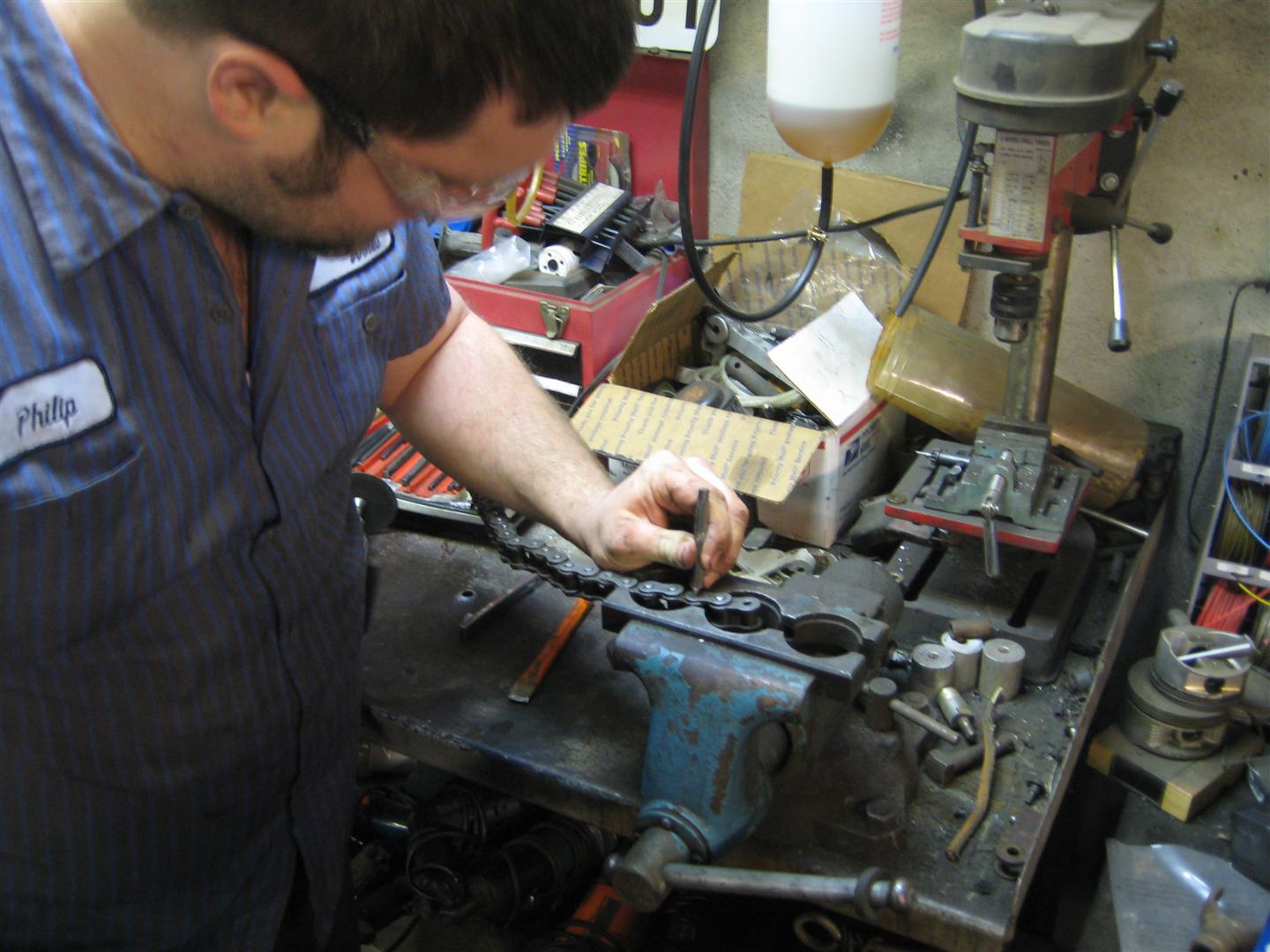
Philip took the old sprocket to the bearing supply house to find a replacement. We also did some measuring to determine roughly how long of a chain we needed. He was able to order the parts easily enough and a couple days later we were going back together with it. First the new sprocket was installed in reverse order of the disassembly. Next, we needed to cut the chain to the correct number of links to obtain the proper tension. Below you see Philip removing excess links in the chain before installation.

Removing Chain Links

Then he installed it. The next two photos show the lower and upper sprockets with the new chain installed.

New Lower Sprocket & Chain

Upper Sprocket New Chain

And that wraps up the drive chain installation. This thing will cover some ground now. I’ll put it this way, in 4th gear it runs as fast as you would want to go on a machine with hydraulic steering and no suspension. Anyway, running it as such seemed to amplify an existing problem we’ve been having with the engine, and that is the backfire from the exhaust when it’s under a load. It encounters a severe power loss when this happens. We’ve adjusted the ignition timing to no avail, so we’re leaning toward the possibility of carburetor problems or a sticking exhaust valve. But that’s for another day. Maybe sometime down the road you’ll see posts on the engine repair and of course the cosmetic restoration. But in the mean time, the machine still works good enough for the occasional small job.


January 16, 2013

2012 In Review

Filed under: Uncategorized — Nicholas Fluhart @ 10:19 pm

The WordPress.com stats helper monkeys prepared a 2012 annual report for this blog.

Here’s an excerpt:

4,329 films were submitted to the 2012 Cannes Film Festival. This blog had 18,000 views in 2012. If each view were a film, this blog would power 4 Film Festivals

Click here to see the complete report.

January 13, 2013

Ditch Witch R40: Trenching Job

Filed under: Project: Ditch Witch,Trucks & Equipment — Nicholas Fluhart @ 5:06 pm

Well, after a successful first run, it wasn’t long before Philip had a job lined up for the R40. He’s building a shop and needed to cut a trench for electrical utilities. Before heading to the work location, we went over the machine and hit all the grease points, changed the fluids, and tightened the chain. Ready for business.

The trench was to be 80 feet in length through very dense clay, which is much more difficult to cut than the soil we tested the machine in at my facility. Of further challenge was the depth of the trench which was to be 30 inches. We will be trenching from the building up to the white stake in the ground seen in the photo below.

Job Site

We began cutting at the building where the power meter would be located. The operator’s manual recommends starting the trench about one foot from the slab of the building in case the chain snags something hard fixed in the ground and pulls the entire machine backward and subsequently into the side of the building. This proved to be good advise. Since this area was previously heavily wooded, there were a few roots that were too big to trench through, so we cut them manually. In the photo below, you’ll see the starting point and you’ll see how hard the ground was.

Starting Point

The chain essentially carved through it, bringing up shavings of clay and the auger neatly piled the small clumps beside the trench.

Trenching

It was very slow going, and we had to use a low trenching gear and a very, very slow wheel speed. In fact, we had to be careful to keep the trenching from rattling the tractor to pieces. It rattled the bottom cap off of the air cleaner, and below you see me reattaching it while Philip continues the trench.

Reinstalling Air Cap

Finally, we were able to complete the trench without any problems from the Ditch Witch. Below you can see the trench and the types of hard, dense clay we carved through represented by the different colors of the material.

Trenching Through Clay

Next, we begun to assemble and lay the conduit for the electrical wire. To meet code, it requires a two part epoxy to be used in the joints. Below you see them applying the epoxy to assemble the conduit. Then it’s just a matter of setting it off into the trench.

Assembling the Conduit

Once the conduit is set in the trench, we can begin backfilling. Philip uses the four-way blade on the front of the Ditch Witch to backfill.

Backfilling

Below you’ll see the finished product. Now we’re ready to place a string into the conduit and await the power company to come and run the electrical wires to the meter.

Finished Backfilling

There are a number of ways to run the wire through the conduit. You generally place a string through first. This can be done by either attaching a vacuum at one end of the pipe and sucking the string through (I’ve even seen someone tape a ping pong ball to the end of the string and reverse the vacuum which would blow the ball through, bringing the string with it) or by using a type of snake. Once you get your string through, it’s just a matter of tying the string to your electrical wires and pulling them through.

Machine Analysis: Overall, everything went well with the machine. I was very impressed. This was an exceedingly hard job for the machine, and after having been setting up for years before this job, the Ditch Witch did it almost flawlessly. However, such a heavy load on the engine as this job placed on it revealed the need for additional fine tuning. We seem to be getting a backfire through the exhaust under heavy load, which was most of the time here. This could be caused by a couple of things: Either the carburetor main jet is a little lean which causes a “lean pop” (this can be determined by inspecting the spark plugs), or the ignition timing is slightly off which can be adjusted at the distributor. Whatever the case, it should be a relatively easy fix…I hope.

Until next time…

October 21, 2012

Ditch Witch R40: First Run

Filed under: Project: Ditch Witch,Trucks & Equipment — Nicholas Fluhart @ 7:51 pm
Tags:

A while back, I posted about the Ditch Witch R40 my friend Philip picked up with the intention of doing a partial restoration. A lot has happened since then, and I decided to give it a spot on my blog. To pick up where I left off, Philip brought the machine to my shop where we would have an endless supply of tools. The first order of business was to get the engine running properly so we could actually operate the machine to see if there were any other issues and proceed with the project. Knowing that there were a couple of stuck valves, Philip proceeded with removing the cylinder heads to assess if the valves were damaged or just stuck with carbon. Upon removal of the heads, he discovered the latter was true. Using penetrating oil he freed the stuck valves, then cleaned the gasket surfaces. That was a fairly easy fix for the valves, however, when removing the rusty head bolts, one of them broke off in the cylinder…and this presented a challenge.

Since there was about 1/4 inch of the bolt sticking out of the cylinder, we had a few options. We started with the easiest solutions, and then worked our way to the more complex. First we tried using a stud extractor, but we couldn’t get enough of the stud into the tool. Second, we tried vice grips and applied heat to the area around the stud. That didn’t work either. The third attempt was to weld a nut onto the end of the stud and use a wrench to remove it. No good. The stud just kept breaking off leaving us with a shorter and shorter area to grip. After much deliberation, it was decided to drill the stud out. Philip flattened the top of the stud with a grinder. Then he reinstalled the cylinder head to use the bolt hole in the head as a guide to center punch the stud in the cylinder. Using a hand drill, it is very difficult to drill completely straight. To counter that challenge, Philip built a tool. Using a lathe from his machine shop, he built a drill bit guide which would fit into the bolt hole on the head and guide the drill bit straight into the stud in the cylinder. This would help ensure not to drill off center and damage the bolt hole in the cylinder. I’ve posted a picture of the guide and bit below.

That did the trick. He drilled the broken stud out of the cylinder and cleaned the threads with a tap. Now it’s just a matter of cleaning everything, fitting the new gaskets he ordered, and reinstalling the heads with new bolts.

Now it’s time to reinstall the engine air shrouds and covers. The Wisconsin engine is an air cooled unit, and it is important to have all the shrouds installed to maintain proper air flow across the cooling fins. We also install thicker exhaust gaskets as the exhaust manifold has apparent warped slightly. The thicker, crushable gaskets, which are actually some motorcycle exhaust gaskets I had, did the trick nicely. We then checked fluids, installed a new fuel line, battery, and some other odds and ends.

We still have the problem of the broken drive chain which connects the transmission and transfer case and subsequently drives the wheels. However, we can still run and drive the machine by using the crowd control which operates the hydraulic motor on the transfer case. This is used for trenching speed only, so it will be very slow. Nonetheless, it should work fine. And…

Success! The engine fired up, and the hydraulics and trencher work great. Oh course, we couldn’t resist cutting a test trench in my back yard, so Philip jumped on the machine and made a go at trenching and backfilling. Check out the video below:

This was a successful test run. Other than the above noted drive chain and the brake master cylinder, there is nothing else wrong with this machine. It won’t be long and it will be ready for its first official trenching job.

Until then…

UPDATE: Check out the first job here.

October 3, 2012

2002 F-150 4.2L Intake Manifold Gaskets

Filed under: Daily Driver,Day to Day — Nicholas Fluhart @ 3:36 pm
Tags: , ,

Well, after ten years of trouble free service, my check engine light came on. I ran the codes and found that the intake manifold gaskets were apparently sucking air and causing a lean condition. The truck ran fine, but the problem was enough to trip the light. After doing some research, I learned that this is a common problem with the 4.2L engine. Alldata had a technical service bulletin on it. Fortunately, the problem is not the lower manifold gaskets between the manifold and the heads. However, it’s the upper manifold gaskets and the two-piece plenum gaskets along with the isolator bolts. In and of itself, that’s not too bad to fix, but the engine is partially under the firewall of the cab which makes access to the upper manifold very limited.

I was able to use a series of universal joints and a range of extensions and remove the upper plenum half without too much hassle, but it wasn’t easy getting to the rear bolts. Once removed, I saw no sign of leaks…yet.

So then I ventured lower. Once the upper half is off it gets pretty easy. I removed the isolator bolts and the bottom half comes off easy enough.

BINGO! You can see where the old gaskets were leaking. Also, the rubber (or what once was rubber) seals on the isolator bolts were as hard as concrete. No one had the isolator seals in stock, but Ford had the entire bolts which were expensive, but I was able to get them the day of the repair so I went with it. In the photo below you can see the difference in material in the seals on the bolts.

Now it’s just a matter of cleaning up the manifold parts and installing the new o-ring gaskets. Then it goes back together the same way it came apart.

Now is also a good time to clean the throttle body and idle air control assembly, and if it needs it, it would be easy to route plug wires at this time. However, I’ve only got about 20K miles on this set of wires, so I’ll let ’em ride. And back together it goes…

That’s pretty much it. It was challenging to start the engine, mainly due to all the carburetor cleaner I had sprayed into the ports had partially fouled the plugs I think, but once it cranked she cleared up and ran great. Now it’s ready to go…and no more check engine light!

Until next time…

« Previous PageNext Page »

Blog at WordPress.com.